Get in Touch with Taiguo


A heat transfer coefficient describes heat crossing a surface per unit area and temperature difference. Use h for one fluid-to-surface interface and U for an assembly such as a heat exchanger. Both use W/(m² K); a useful value requires a stated temperature reference, area, and operative state.
Two suppliers may quote different U values for the same exchanger since one may use the inside tube area and the other the outside area. Comparing UA, the overall thermal conductance in W/K, removes that particular area convention mismatch. The calculations that follow show how to compare coefficients and where more heat-transfer area would be beneficial.
By Candy · Updated November 2026
What Is a Heat Transfer Coefficient?
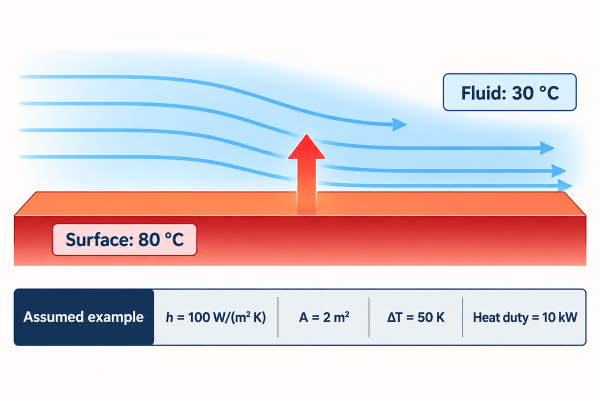
The convective heat transfer coefficient h connects the heat flux of a surface to the temperature difference between that surface and a specified fluid reference. For a given surface, a higher h means that a larger convective heat flux is attainable at the same temperature difference. Unlike a property of a material, the coefficient indicates the interaction of the surface with a moving fluid.
Equation Q″ = h(Ts – Tb) relates the heat flux to the temperature difference. Here, Q″ is flux in W/m², Ts is the surface temperature, and Tb is the bulk-fluid temperature. For a uniform surface, the relation is Q̇ = hA(Ts – Tb). Purdue’s mechanical engineering equation sheet gives the relation and its dimensionless form.
Assume h = 100 W/(m² K), A = 2 m², a surface at 80 °C and a fluid reference at 30 °C. The temperature difference is 50 K, so Q̇ = 100 × 2 × 50 = 10,000 W, or 10 kW. For a surface with a variable temperature or local h, we integrate the local heat flux or use an average defined for that particular case.
What is heat convection?
Heat convection occurs when a surface exchanges heat with a fluid in motion. Molecular conduction acts near the wall, while energy is transferred to the surrounding flow by the movement of the fluid. A fan or a pump creates forced convection, while buoyancy creates natural convection because warmer and cooler fluid have different densities.
Imagine a hot pipe in still air. Cooler air moves in, and warm air rises around the pipe, without a fan. Blowing air across it changes the boundary layer and the resulting h; the pipe’s metal conductivity has not changed merely because the fan started.
Heat Transfer Coefficient vs Thermal Conductivity: h, U and k
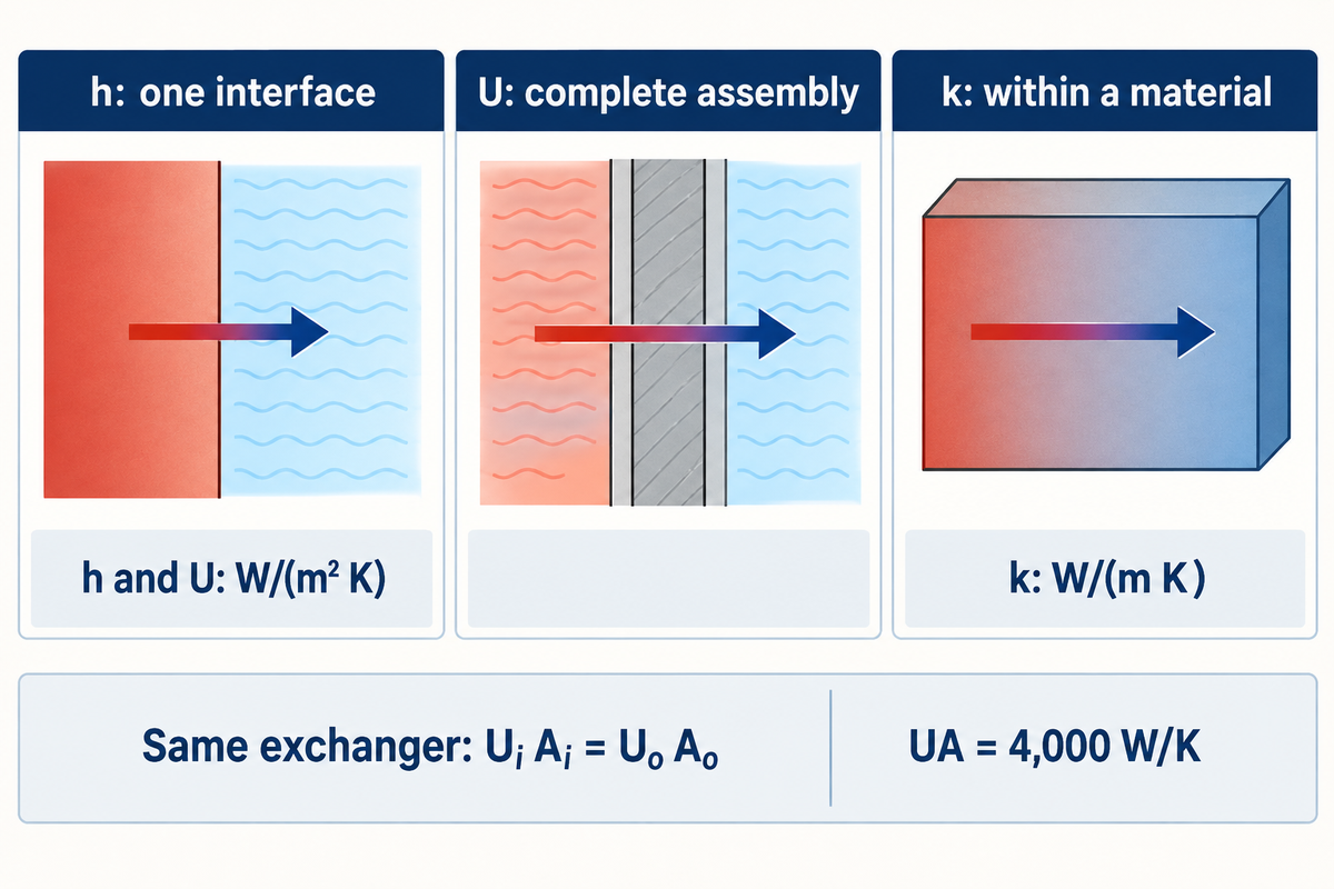
Thermal conductivity k defines conduction within a material, h defines convection across a surface, and U describes the combined resistance across an assembly. Their units help distinguish them: h and U use W/(m² K), while k uses W/(m K). Replacing one with the other changes the physical meaning of the calculation.
| Quantity | What it describes | Required reference |
|---|---|---|
| h, W/(m² K) | One convective interface | Surface and fluid temperatures; local or average area |
| U, W/(m² K) | Overall heat-transfer path | Inside, outside or other defined area; effective mean temperature difference |
| k, W/(m K) | Conduction through a material | Material, temperature and conduction direction where relevant |
Heat-Exchanger Notes at MIT obtain the combined resistance using tube geometry. Their notation is different from some industrial data sheets, so be sure you identify the physical boundary before comparing symbols. Some arrangements of equipment are covered in our article on industrial heat-Exchangers.
For the same exchanger, UiAi = UoAo. Suppose Ui = 500 W/(m² K) on 8 m² of inside area: UA is 4,000 W/K. On an outside area of 10 m², the identical conductance is Uo = 400 W/(m² K).
Another distinction for an air-cooled finned surface is that the total fin area and bare tube area aren’t the same, and fin efficiency affects useful heat transfer. Consider the area convention and surface efficiency together. A smaller U, quoted on a larger reference area, can explain the same performance.
Heat Transfer Coefficient Units and Heat-Rate Equations
One BtuIT/ (h ft² °F) = 5.678263 W/(m² K) according to the NIST coefficient-of-heat-transfer conversion table. The Celsius and Kelvin temperature differences have the same value. Maintain consistency in time, area, and temperature differences throughout the heat rate equation.
A practical example is 100 BtuIT/(h ft² °F), which becomes approximately 568 W/(m² K). In metric form, 1 kW/(m² K) is 1,000 W/(m² K).
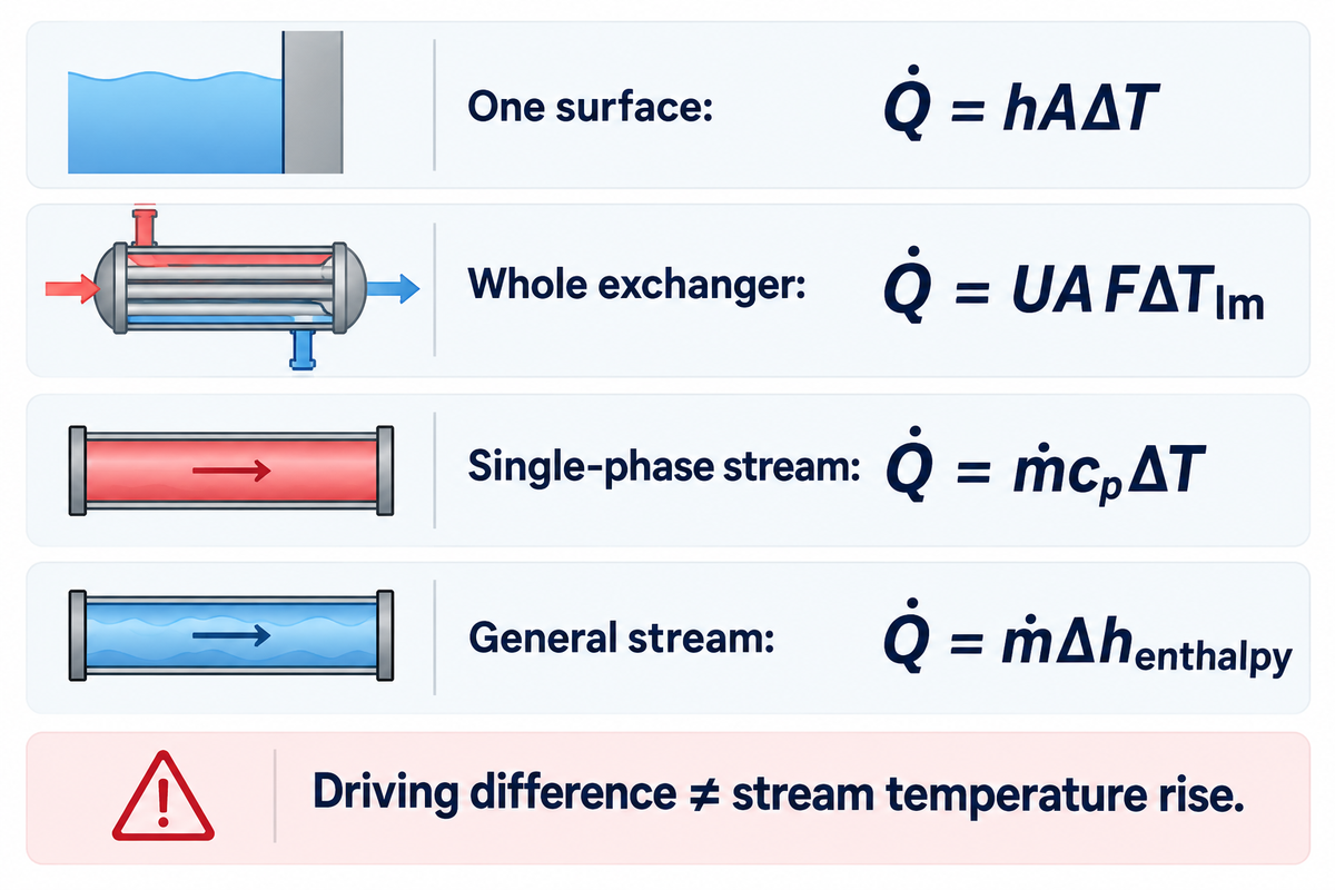
- One surface: Q̇ = hAΔTsurface-fluid.
- Whole exchanger: Q̇ = UA FΔTlm, using the appropriate log mean temperature difference and flow-arrangement correction F.
- Single-phase stream: Q̇ = ṁcpΔTstream, with a representative heat capacity for that temperature interval.
- General stream enthalpy balance: Q̇ = ṁΔhenthalpy, including phase change where applicable.
The stream temperature rise is different from the temperature difference driving heat through the wall. A water stream can rise by 20 K while the average difference between hot and cold streams is 40 K. Replacing the second temperature difference with the first, one would infer twice as much U in the example.
In the enthalpy equation, h_enthalpy has units of J/kg and is unrelated to the film coefficient h. For steam, use the difference in inlet and outlet enthalpy including condensate cooling and/or superheat if it exists. Our guide to steam enthalpy on a Mollier diagram explains the notation.
Select a Convective Heat Transfer Coefficient for the Flow
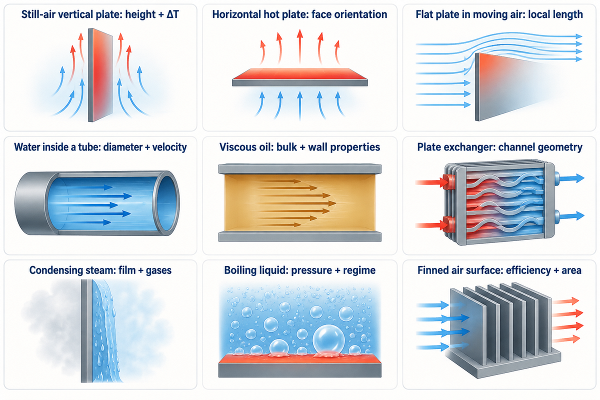
To start, figure out what moves the fluid, and where the surface is. Then select the characteristic length and fluid-property temperature required by the chosen relationship.
| Application | Coefficient basis | Input that changes the selection |
|---|---|---|
| Vertical plate in still air | Natural convection over the plate | Plate height and surface-to-air temperature difference |
| Horizontal hot plate | Natural convection for its orientation | Heated face pointing upward or downward |
| Flat plate in moving air | External forced convection | Distance from the leading edge and boundary-layer regime |
| Water inside a tube | Internal forced convection | Diameter, velocity and thermal entrance length |
| Viscous oil inside a tube | Internal flow with appropriate property treatment | Bulk and wall temperatures; laminar or turbulent regime |
| Flow through a plate exchanger | Channel-specific relationship | Channel shape, spacing and flow distribution |
| Steam condensing on a surface | Condensation-side h | Film drainage, orientation and noncondensable gases |
| Liquid boiling at a wall | Boiling relationship | Pressure, heat flux and boiling regime |
| Finned air-cooled surface | Air-side h with a stated surface basis | Fin geometry, efficiency and air velocity |
The logic for selection follows the separate cases of convection in the Purdue equation sheet. Don’t bring in a flat plate characteristic length for an internal tube case. A coefficient measured in one channel requires a flow-distribution check to represent the entire exchanger.
Many correlations predict the Nusselt number, Nu. Recover h from h = Nu kfluid/L. With assumed Nu = 50, k fluid = 0.60 W/(m K) and L = 0.020 m, the result is 1,500 W/(m² K); this arithmetic presumes that Nu was obtained from a valid correlation for the case.
In finite element analysis (FEA), assigning h specifies a convection boundary condition; the solver doesn’t verify the chosen coefficient simply by converging. Predicted internal temperature and temperature distribution still depend on that input. For other convective problems, such as electronics cooling, separate convective heat transfer from heat leaving through supports or radiation.
“Each choice of reference temperature defines a different h”
Moffat’s experimental comparison illustrates the significance of using the same temperature reference when comparing h values. Label each measurement or prediction with its reference to distinguish the bases being compared. Use this technique when checking a loop supplied by industrial hot-water boiler systems.
Heat Transfer Coefficients for Steam, Water, Air and Oil
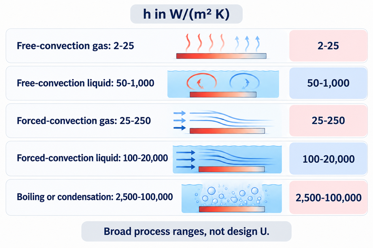
Typical convection coefficients span from 2–25 W/(m² K) for gases in free convection to 2,500–100,000 W/(m² K) for boiling or condensation in the textbook table reproduced by Michigan Technological University. For gases under forced convection, the same table lists 25-250 in the same units. These broad h ranges classify processes; a fluid name alone can’t select the operating point within them.
| Process | Fluid class | h, W/(m² K) |
|---|---|---|
| Free convection | Gases | 2–25 |
| Free convection | Liquids | 50–1,000 |
| Forced convection | Gases | 25–250 |
| Forced convection | Liquids | 100–20,000 |
| Boiling or condensation | Phase-changing fluid | 2,500–100,000 |
The handout credits Fundamentals of Heat and Mass Transfer , sixth edition, 2007. A heat transfer textbook offers a useful plausibility check, but the natural convection heat transfer coefficient for a specific surface still requires its dimensions and orientation. An exposed vertical wall and the underside of a horizontal hot plate have different buoyancy-flow configurations.
What is the heat transfer coefficient of steam?
Condensing steam belongs to the phase-change category, for which the broad textbook range for boiling or condensation is 2,500 to 100,000 W/(m² K). Steam that stays in the gas phase requires a gas-convection calculation, instead. The overall coefficient of a steam condensing exchanger includes wall and process side resistances as well as the steam side film.
Air mixed with steam can accumulate near the condensing interface. Sparrow and Lin’s condensation research describes the resulting reduction in vapor partial pressure and condensation temperature. Using total mixture pressure like a pure steam pressure can provide an incorrect temperature driving force.
Water and thermal oil calculations rely on the viscosity and other properties of the working fluids at the specified operating conditions prior to selecting the flow correlation. A cold oil start-up can occupy a different flow regime from hot operation. Keep utility selection separate from coefficient calculation; our thermal oil boiler selection guide covers the heating-system choices.
Overall Heat Transfer Coefficient: Tube Geometry and Fouling
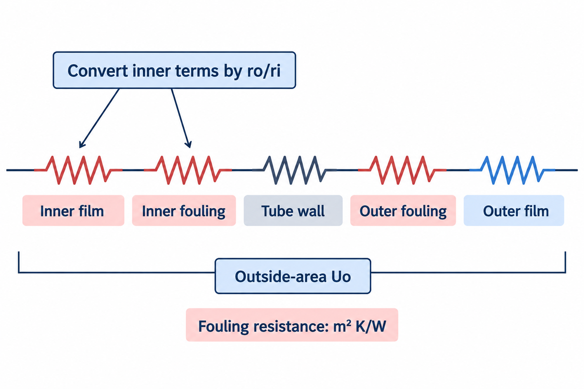
A cylindrical tube needs a logarithmic wall resistance term and an area conversion from inside to outside. For an outside area Uo, the inner film and inner fouling resistances are multiplied by the outside to inside radius ratio. Adding equal area plane wall terms without that conversion can give a false overall coefficient.
1/U_o = r_o/(r_i h_i) + (r_o/r_i) R_f,i + r_o ln(r_o/r_i)/k_wall + R_f,o + 1/h_o.
Here the area-normalized fouling resistances Rf,i and Rf,o use m² K/W on their respective surfaces. This is the MIT cylindrical resistance model with the two fouling terms added on matching areas. For surfaces that are finned or complex, use the corresponding effective area model.
Take an assumed clean tube with ri = 0.010 m, ro = 0.012 m, kwall = 16 W/(m K), hi = 1,000 W/(m² K) and ho = 2,000 W/(m² K). The outside-area resistance is 0.001200 + 0.0001367 + 0.000500 = 0.0018367 m² K/W. Its reciprocal gives Uo ≈ 544 W/(m² K).
Fouling adds resistance, but changes in flow and/or properties can also lower U. Compare clean and operating values at matched conditions before attributing differences to fouling.
Thermal radiation of a furnace requires a separate exchange model. The International Flame Research Foundation differentiates radiant heat flux from total heat flux consisting of radiation and convection. Treating radiation as another ordinary series film resistance would overlook that physical distinction.
Calculate the Overall Heat Transfer Coefficient from Operating Data
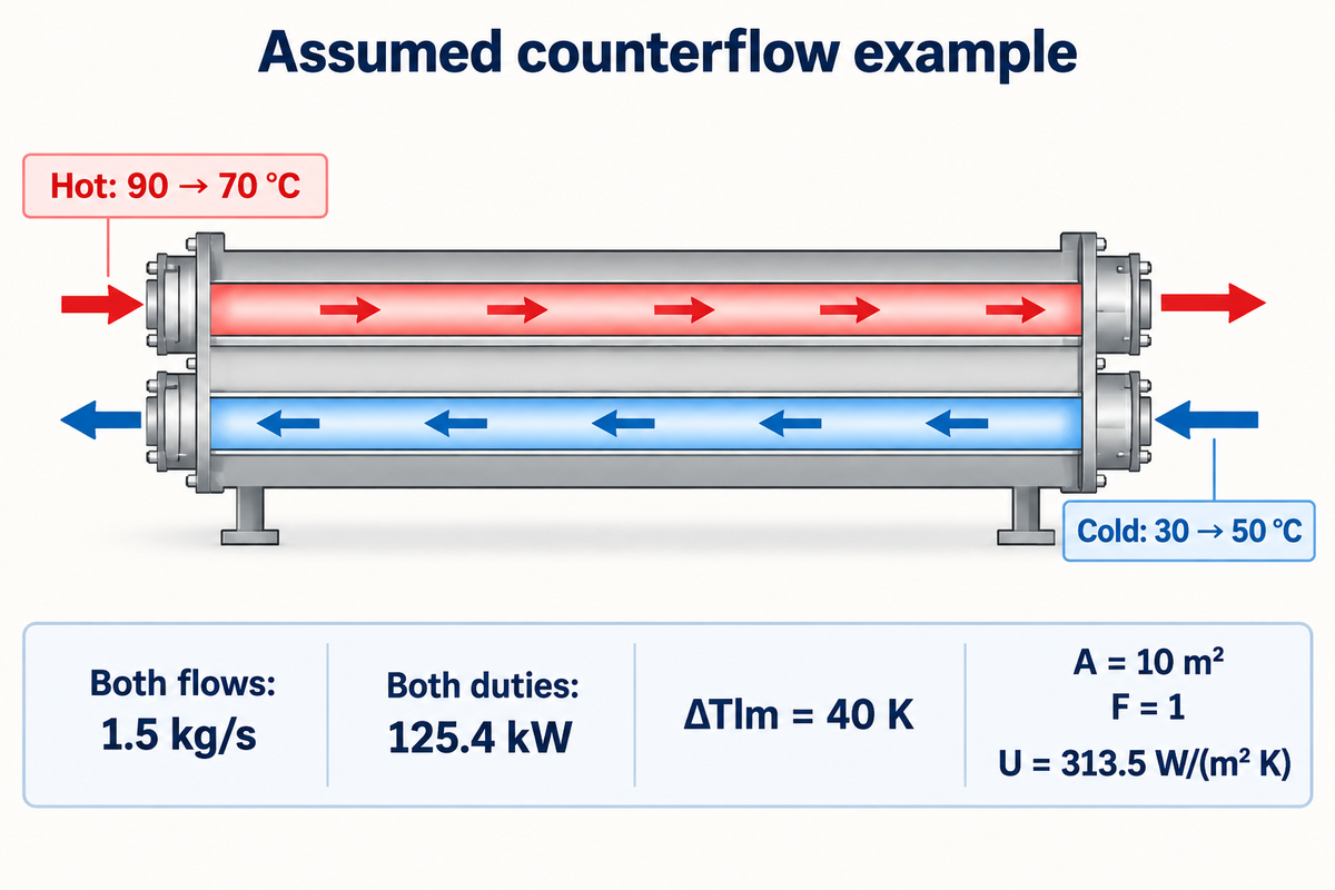
An operating U is calculated by dividing heat duty by the chosen area and effective mean temperature difference. First calculate the hot and cold side duties separately and then identify the flow arrangement. The following U Value Measurement Worksheet provides a complete example of counterflow with assumed readings and a common area basis.
Assumed inputs: steady single-phase water flow, negligible heat loss, constant c p = 4.18 kJ/(kg K) on both sides, ideal counterflow with F = 1, and 10 m² of heat-transfer area. These inputs show the method; they aren’t Taiguo equipment test results.
| Entry | Example value or calculation | What to record on site |
|---|---|---|
| Hot-stream temperatures | 90 °C in; 70 °C out | Locations, timestamps and sensor calibration |
| Cold-stream temperatures | 30 °C in; 50 °C out | Locations and matching operating interval |
| Hot mass flow | 1.5 kg/s | Meter basis and uncertainty |
| Cold mass flow | 1.5 kg/s | Independent reading and uncertainty |
| Assumed mean heat capacity | 4.18 kJ/(kg K) | Fluid composition and property-temperature basis |
| Hot duty | 1.5 × 4.18 × (90 − 70) = 125.4 kW | Heat loss and phase-change treatment |
| Cold duty | 1.5 × 4.18 × (50 − 30) = 125.4 kW | Compare with hot duty before combining results |
| First terminal difference | 90 − 50 = 40 K | Correct counterflow endpoint pairing |
| Second terminal difference | 70 − 30 = 40 K | Positive temperature-driving differences |
| Log mean temperature difference | 40 K | Equal-endpoint limit used here |
| Area and correction factor | A = 10 m²; F = 1 | Area drawing and actual flow arrangement |
| Overall coefficient | 125,400/(10 × 1 × 40) = 313.5 W/(m² K) | U uncertainty and operating conditions |
For unequal positive end-point differences, ΔTlm = (ΔT1 – ΔT2) / ln(ΔT1/ΔT2). In this case, if both end-point differences are 40 K, its limiting value is 40 K; don’t evaluate the literal expression as 0/0. If, however, the end-point differences are assumed as 50 K and 30 K, respectively, the log mean is about 39.15 K.
Suppose the hot-side calculation instead gives 125.4 kW and the cold-side calculation gives 112 kW. Their difference is about 10.7% of the hot duty. Check sensor offsets, flow measurement, heat loss and operating stability before taking an average of the duties. Judge the discrepancy against the calculated measurement uncertainty.
Even matching duties can share measurement bias. NIST’s guidance on uncertainty propagation accounts for covariance between correlated inputs, which is important when the same temperature readings affect both the duty and the mean driving difference. Report an uncertainty interval based on the actual instruments and calculations, and do not treat every shown decimal as measured precision.
Stored energy and thermal capacitance also enter the balance for a batch vessel. A transient heating curve is a different experiment from the steady-flow case represented by the worksheet. Resolve the storage and heat loss terms explicitly and use them to estimate a variable coefficient.
Thermal Resistance: Find the Limit Before Adding Area
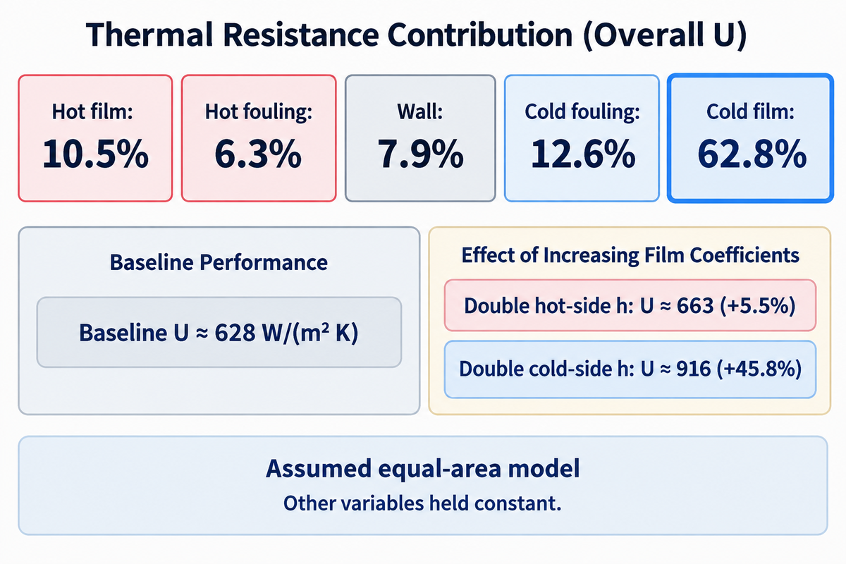
The greatest known thermal resistance offers the greatest opportunity for improvement when other terms remain the same. A 5-Resistance Heat Transfer Budget separates the two fluid films, two fouling allowances and wall resistance. Construct it from independent component estimates; measured total U alone can’t reveal how that resistance is apportioned.
Assumed equal-area example: hot-side h = 6,000 W/(m² K), cold-side h = 1,000 W/(m² K), wall thickness = 2 mm, wall conductivity = 16 W/(m K), and the two fouling allowances shown below. For this plane-wall illustration, 1/U = 1/hhot + Rf,hot + δ/k + Rf,cold + 1/hcold.
| Component | Resistance, m² K/W | Share of total |
|---|---|---|
| Hot fluid film | 1/6,000 = 0.0001667 | 10.5% |
| Hot-side fouling allowance | 0.0001000 | 6.3% |
| Wall | 0.002/16 = 0.0001250 | 7.9% |
| Cold-side fouling allowance | 0.0002000 | 12.6% |
| Cold fluid film | 1/1,000 = 0.0010000 | 62.8% |
The total resistance is approximately 0.0015917 m² K/W, giving U ≈ 628 W/(m² K). Therefore, doubling the hot-side h gives U ≈ 663 W/(m² K), a 5.5% increase. Doubling the cold-side h gives U ≈ 916 W/(m² K), a 45.8% increase.
A comparison for a plant manager focuses on the larger cold-side film resistance. Finance can compare the cost of improving that side to the cost of extra area, while procurement requests the associated pressure-drop and cleaning implications. The arithmetic holds the other variables constant; a change in flow or geometry can change many of the variables at the same time.
Area follows A = Q̇/(U FΔTlm). If U falls to 80% of its original value while duty and effective mean temperature remain fixed, the required area rises to 1/0.8 = 1.25 times the original: 25% more area. The cost of the area depends on the arrangement of tube or plate, the materials used, the pressure rating of the exchanger and the fabrication. Maintaining velocity may require a different passage layout, while allowable pressure drop constrains that redesign; area alone can’t determine the price change.
The addition of parallel flow passages can decrease velocity per passage and change h, pressure drop, and fouling behavior. Evaluate proposed changes with a recalculated thermal rating to approve an increase in area. Keep local exchanger calculations separate from the thermal power plant heat flows and the overall energy balance.
Heat Transfer Coefficient Inputs for a Supplier Calculation

A good supplier calculation starts with the heat duty, both fluid descriptions, operating temperatures and allowable pressure drop. Compare supplier quotes for U with the same area basis and clean versus fouled conditions. This information lets engineering evaluate the thermal performance while procurement evaluates the same duty and acceptance conditions.
Include in the calculation request
- Fluid composition, phase and expected operating-property range on both sides.
- Required duty; normal, start-up and minimum-flow conditions; which outlet temperature must be achieved.
- Mass flow and inlet temperatures, with known outlet measurements identified separately.
- Allowable pressure drop, available utility conditions and connection constraints.
- Heat-transfer area and its definition; tube or channel geometry and wall material.
- Fouling assumptions, cleaning access and the proposed performance-test basis.
- Quoted h values, overall U, correction factor and calculated duty under the same conditions.
For a contractual performance test, the ASME PTC 12.5 publisher page identifies Single Phase Heat Exchangers, PTC 12.5-2000 (R2025). Its stated scope is single-phase service; a condensing-steam application needs an applicable testing basis. Agree the procedure and measurement uncertainty with the supplier prior to the acceptance test.
Taiguo Boiler provides product families of steam, hot water and thermal oil boilers. Send the process-side duty and temperature requirements along with the utility request, so a heat source capacity can be assessed against the actual transfer requirement of the exchanger.
Heat Transfer Coefficient FAQ
Is heat transfer coefficient constant?
The heat transfer coefficient usually changes with operating conditions.
Flow speed, fluid properties, geometry and temperature affect the surface heat exchange. Treating h as constant is a modeling assumption over a stated range, rather than a permanent material characteristic. During a cold start, viscosity can differ from its hot-running value, changing the Reynolds number and the appropriate convection relationship.
Can heat transfer coefficient be negative?
For ordinary passive convection with consistently defined heat-flux direction and temperature difference, h is positive.
A negative calculated result often signals a reversed sign convention, a mismatched reference temperature or an incomplete heat balance. Trace the direction assigned to heat flow and the temperatures used in the denominator before interpreting it. A signed heat rate can be negative even when the physical coefficient remains positive.
Does overall heat transfer coefficient change with temperature?
Overall U can change with temperature as fluid properties, flow behavior and phase change alter the component resistances.
Viscosity changes can be especially relevant when they change the convection regime. Wall conductivity and fouling resistance also belong in the model. Compare values at matched operating conditions and on the same area basis, then use independent process observations to identify which component changed before choosing an intervention.
What is natural convection?
Natural convection is fluid motion driven by buoyancy.
Density differences create the circulation, often when a surface heats the nearby fluid. Geometry, orientation and the surrounding air temperature affect natural convection heat transfer without a pump or fan.
How do you calculate heat transfer coefficient from Nusselt number?
Calculate h = Nu × kfluid/L using the characteristic length defined by the selected correlation.
The correlation supplies the applicable geometry, flow regime and property-temperature convention. A diameter for internal flow and a length along an external plate can’t be exchanged simply because both are measured in meters. This distinction prevents a dimensional-looking but physically wrong calculation in convective heat transfer problems.
Is U a heat transfer coefficient?
Yes. U is the overall heat transfer coefficient.
It combines the relevant resistances for a stated assembly and area. The film coefficient h describes one surface-to-fluid interface instead.
How does a heat exchanger work?
A heat exchanger transfers energy between streams at different temperatures.
In an indirect exchanger, heat crosses from one fluid through a separating wall to the other. Overall U combines the relevant resistances, while area and the temperature driving force determine the heat duty together with it. The stream energy balances must also agree with that transfer calculation; outlet temperatures can’t all be chosen independently.
Discuss Your Process Heating Requirements

Provide your fluid requirements, heat duty, and temperature to Taiguo Boiler along with your available utilities. Provide the rating or operating worksheet of the current exchanger if available. Discuss a process-heating requirement with a clear duty basis to aid equipment selection.
References & Sources
- Purdue University, Heat Transfer Area Exam Equation Sheet.
- MIT, 18.5 Heat Exchangers.
- Michigan Technological University, Typical Values of the Convection Heat Transfer Coefficient, credited to Incropera et al., 2007.
- NIST, Guide to the SI, Appendix B.9: Conversion Factors.
- Robert J. Moffat, Evaluation of Different Heat Transfer Coefficient Definitions, 1995.
- E. M. Sparrow and S. H. Lin, Condensation Heat Transfer in the Presence of a Noncondensable Gas, 1964.
- International Flame Research Foundation, How Do I Measure the Parameters Characterising Radiation Heat Transfer in Furnaces?
- NIST, Technical Note 1297, Appendix A: Law of Propagation of Uncertainty.
- ASME, Single Phase Heat Exchangers, PTC 12.5-2000 (R2025).