Get in Touch with Taiguo


A boiler superheater is a tubular heat exchanger that adds sensible thermal energy to saturated vapor leaving the steam drum. Raising steam above its boiling point at constant pressure eliminates entrained water droplets before turbine expansion. Conversely, Spirax Sarco’s steam heat-transfer guide reports shell-and-tube overall U values dropping from 500 W/(m²·°C) on saturated steam to 100 W/(m²·°C) on superheated steam.
Specifying superheat therefore splits industrial steam generation into two distinct operating camps. Power generation turbines and long yard headers need a dry gas margin, while jacketed vessels transfer heat faster with dry saturated steam. Below, our Three-Boundary Superheat Selection Matrix maps expansion dryness, part-load radiant-convective temperature curves, and ASME tube-wall oxidation ceilings so engineers lock accurate boiler specifications.
By Candy · Updated November 2026
What Does a Superheater Do in an Industrial Steam Boiler?
In an industrial boiler, a superheater is a device that heats saturated vapor to a higher temperature above its saturation temperature at constant pressure. Dry steam leaves the drum separator and enters coil loops exposed to hot flue gas. Removing suspended moisture protects high-speed rotating equipment and prevents condensate buildup along long distribution piping.
How Superheater Coils Convert Wet Vapor into Dry Superheated Steam
Inside the boiler drum, water and vapor coexist at the saturation point. Adding heat to that drum mixture evaporates more liquid and doesn’t raise the steam temperature. To heat the steam further, mechanical baffles and chevron dryers first strip entrained moisture from the steam generated in the riser bank.
That vapor then enters an external bank of tubes positioned in the combustion gas pass. Exposed coils absorb heat from hot combustion gases across the metal wall into the single-phase gas flow. Residual mist evaporates first, and additional sensible energy raises the final degrees of superheat.
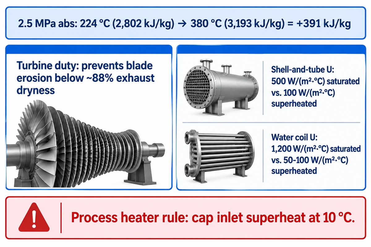
Example: Assume a cogeneration header operates at 2.5 MPa absolute, where saturation temperature is approximately 224 °C and dry saturated enthalpy is 2,802 kJ/kg. Heating that vapor to 380 °C yields 156 K of superheat and raises enthalpy to roughly 3,193 kJ/kg. Each kilogram of steam carries 391 kJ of extra sensible energy before condensation begins.
Early railway engineers solved cylinder condensation in a steam locomotive by routing Schmidt type U-tubes in enlarged fire flues. Reciprocating steam engines needed only moderate superheat to reduce port heat loss. Modern utility and cogeneration plants raise pressures and temperatures even higher to drive multi-stage axial rotors in steam turbine Rankine cycle power generation systems.
When Should a Plant Use Superheated Steam Instead of Saturated Steam?
Use superheated steam for turbine electricity generation, direct high-temperature drying, and long pipeline runs; use dry saturated steam for indirect heaters. As steam expands through turbine stages, pressure and enthalpy fall together. Entering a turbine at saturation causes early condensation, and high-velocity droplet impact erodes low-pressure turbine blades once exhaust dryness drops below roughly 88%.
Indirect process heating reverses that verdict. Condensing vapor releases large latent heat instantaneously at a constant wall temperature. Superheated gas behaves like a dry gas insulator until it cools down to saturation. Spirax Sarco reports horizontal water-coil U values falling from 1,200 W/(m²⋅°C) on saturated vapor to 50-100 W/(m²⋅°C) on superheated gas. Their guide recommends capping process heater inlet superheat at 10 °C.
| Plant Duty or Coil Configuration | Boundary 1 & 2: Heat-Transfer or Part-Load Slope | Boundary 3: Reported U Value or ASME Alloy Ceiling | Superheat Specification Verdict |
|---|---|---|---|
| Back-pressure cogeneration steam turbine | Isentropic enthalpy drop across rotor stages | SA-213 T11/T22 coils up to 552–580 °C metal oxidation limit | Recommended (mandatory for blade protection) |
| Condensing utility steam turbine | Deep vacuum Rankine cycle efficiency gain | SA-213 TP304H/TP347H finishing loops up to 704 °C (1300 °F) | Recommended (high superheat temperature) |
| Long inter-building steam header (>300 m) | Sensible buffer against line radiation loss | SA-192/SA-210 carbon steel below 427 °C (800 °F) graphitization | Suitable (desuperheat before indirect users) |
| Shell-and-tube process heat exchanger | Dry-gas cooling penalty vs. film condensation | 100 W/(m²·°C) superheated vs. 500 W/(m²·°C) saturated (Spirax Sarco) | Not Recommended above 10 °C superheat |
| Horizontal heating coil submerged in water | Tube-side condensation into liquid bath | 50–100 W/(m²·°C) superheated vs. 1,200 W/(m²·°C) saturated (Spirax Sarco) | Not Recommended (use saturated steam) |
| Steam-to-fuel-oil coil heater | Viscous oil convection outside tube wall | 20 W/(m²·°C) superheated vs. 150 W/(m²·°C) saturated; coking risk | Not Recommended (risks local oil fouling) |
| Radiant superheater panel | Outlet steam temperature falls as firing rises | High radiant heat flux requires T22 or TP347H alloy margin | Suitable only when paired with convective bank |
| Convective superheater bank | Outlet steam temperature climbs as gas flow rises | SA-210 or SA-213 T11/T22 behind water-wall screen tubes | Suitable for steady base-load boilers |
| Series radiant-convective with interstage spray | Complementary load curves flatten outlet temperature | Interstage spray holds finishing metal below code oxidation limit | Recommended for cycling cogeneration plants |
Radiant, Convective, Platen, and Separately Fired Superheaters Compared
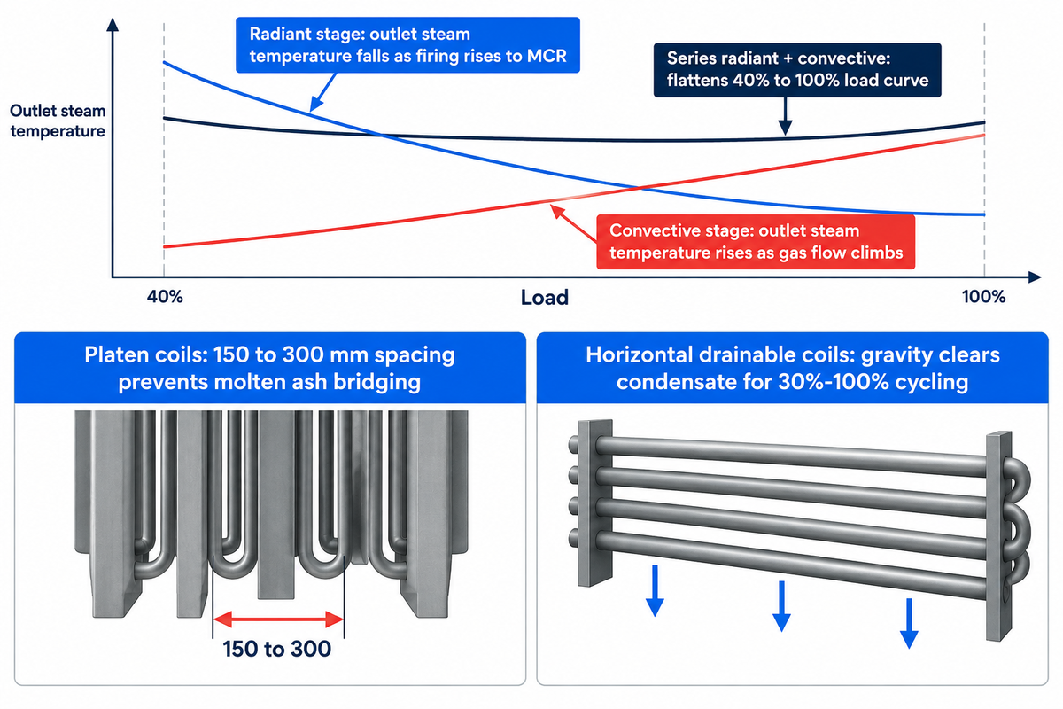
Boiler firing increases from part load to full MCR and radiant superheater outlet temperature falls, while convective outlet temperature rises. Industrial water-tube steam boilers pair the two stages in series to cancel out their opposite load slopes. The USPTO CPC F22G patent classification groups these superheaters by heating method, tube construction, temperature control and location of flue path.
Why Radiant and Convective Superheaters Show Opposite Load Curves
A radiant superheater faces the open combustion flame directly or hangs as wide-pitched furnace division panels. The radiant heat flux grows very little from half load to full load as the flame temperature increases very little. The steam mass flow through the tubes increases from half load to full load and heat absorbed per kilogram of steam decreases.
Convective superheaters sit behind furnace screen boiler tubes where direct flame radiation is shielded. Both flue gas velocity and gas temperature increase as burner firing increases. Convective heat transfer increases faster than steam flow, and unattemperated outlet temperature rises at full load.
Platen superheaters bridge the two zones at the furnace exit. Wide spacing (150 to 300 mm) keeps molten ash from bridging over fuels, captures semi-radiant heat, and minimizes fouling. Separately fired superheaters use a separate combustion system outside the main boiler. Independent firing trims steam temperature cleanly when the load on the main steam fluctuates.
Consider a pulp mill cogeneration plant running at 40% load during a paper machine web break. A stand-alone convective bank loses significant steam temperature when the back-pressure turbine still needs a dry inlet vapor. Pairing a furnace-wall radiant panel ahead of the convective coils flattens that part-load temperature dip and cuts spray water demand at full firing.
Vertical Pendant vs. Horizontal Drainable Superheater Coils
Tube orientation is critical to both structural support and condensate removal at high temperature. Cooled roof penetrations outside of the gas stream are fitted with vertical pendant loops. Eliminating support beams in the hot gas stream was the goal. However, the bottom return bends on boilers trap condensate during shutdown.
Water trapped in the steam loops restricts steam flow during fast restarts. Boil-out needs to be completed first. Horizontal coils are pitched slightly towards the lower drainable headers to allow gravity to drain condensate before light off. Coils are drained horizontally during cooldown if a plant cycles from 30% to 100% load or if the plant completely shuts down. In a base-load situation, solid-fuel units favor ash-shedding pendant panels.
How Water-Tube Boilers Integrate Superheaters Along the Flue-Gas Path
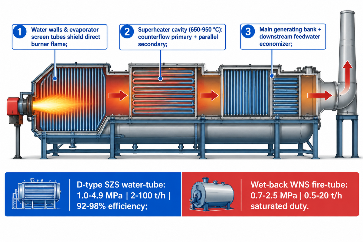
That zone provides flue gas hot enough (650–950 °C) to drive heat transfer without exposing dry-steam tubes to direct burner flame impingement.
Flue-Gas Path Sequence: Furnace Screen, Superheater, Generating Bank, and Economizer
Water walls absorb most of the radiant heat while the water boils and keeps the wall metal at saturation temperature. A few rows of evaporator screen tubes decrease the velocity of the gas and direct it toward the superheater cavity. Behind the superheater, cooler gas crosses the main generating bank and finally enters downstream boiler economizer feedwater heat recovery coils.
Designers also sequence steam flow direction relative to flue gas to protect hot metal. Pure counterflow maximizes the log-mean temperature difference, as derived in MIT’s counterflow heat-exchanger equations. However, pure counterflow places the hottest steam leg outlet in the hottest gas row. Splitting coils into a counterflow primary stage and a parallel flow secondary stage caps the temperature of the peak crown metal.
Why D-Type and Bi-Drum Water-Tube Boilers Own High-Superheat Duty
Shell-type fire-tube boilers store large water volumes inside a cylindrical shell restricted by flat tube-sheet stress rules, so fitting high-temperature coils into a wet-back reversal chamber risks tube-end overheating. D-type water-tube SZS boilers supplied by Taiguo Boiler cover the pressure range of 1.0 to 4.9 MPa, while wet-back WNS fire-tube boilers cover the range of 0.5 to 20 t/h at a pressure of 0.7 to 2.5 MPa.
Achieving 92–98% thermal efficiency, standard packaged SZS skids deliver 2–50 t/h while custom engineered units extend that range from 2 to 100 t/h. High-pressure SZS configurations at 2.45 to 4.9 MPa place superheater modules behind the D-furnace exit screen tubes.
Which Materials Are Used for Superheater Tubes? ASME Alloy Tiers
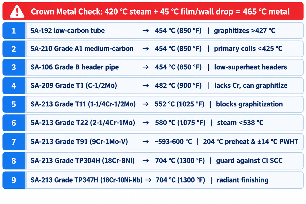
Superheater tube materials progress from ASME SA-192 and SA-210 carbon steel up to 454 °C (850 °F) oxidation limits into chromium-molybdenum and stainless alloys. SA-213 T11 and T22 handle 552–580 °C (1025–1075 °F) metal, while austenitic TP304H and TP347H reach 704 °C (1300 °F). Engineers always select alloys using peak fire-side crown metal temperature rather than nominal header steam temperature.
Why Single-Phase Steam Film Resistance Drives Tube Metal 30–60 °C Above Steam Temperature
Evaporator water-wall tubes enjoy nucleate boiling inside the bore, holding inner metal within a few degrees of water temperature. On the other hand, in a superheater element, single-phase vapor has a much lower film conductance. Heat from 800 °C gas must penetrate through a much thicker boundary layer to reach the core of the steam, thus the gas side of the wall has a much greater temperature difference. Refer to our Engineering Guide, convective heat transfer coefficient and series wall thermal resistance for an explanation of this case.
Applying a steam-film wall temperature margin check prevents premature alloy failure. Assumed inputs: an industrial boiler targets 420 °C outlet steam while local heat flux creates a 45 °C radial drop across the steam film and wall. Fire-facing crown metal reaches 465 °C, pushing plain carbon steel past its 427 °C (800 °F) graphitization limit even though outlet steam reads 420 °C.
“The addition of about 1/2% chromium as an alloying element to steels will prevent the change from iron carbide to graphite. Thus, T-2, T-11, and T- 22 materials with 1/2%, 1-1/4%, and 2-1/4% chromium will not graphitize.”
ASME Tube Metallurgy Ladder: Carbon Steel, Cr-Mo (T11/T22/T91), and Stainless (TP304H/TP347H)
Dr. French’s metallurgical data confirms that alloying steel with at least 1/2% chromium stabilizes carbides and stops weld-zone graphite embrittlement. Ferritic 1-1/4Cr, 1/2Mo (SA-213 T11) and 2-1/4Cr, 1Mo (SA-213 T22) carry most medium-pressure industrial superheater tubes. Creep-strength-enhanced ferritic SA-213 T91 (9Cr, 1Mo, V) cuts heavy header wall thickness nearly in half above 540 °C. However, T91 demands strict 204 °C (400 °F) preheat and ±14 °C (±25 °F) post-weld heat treatment accuracy.
For final steam temperatures below 538 °C (1000 °F), specifying T22 instead of T91 avoids brittle field-repair welds. Once crown metal exceeds 580 °C on T22 or surpasses roughly 600 °C on SA-213 T91 loops, designers transition to 18Cr, 8Ni austenitic grades TP304H or TP347H. Any ferritic-to-austenitic dissimilar metal weld (DMW) uses nickel-base filler (ERNiCr-3) placed in lower-heat-flux zones to limit thermal-expansion fatigue.
| ASME Material Grade | Nominal Alloy Chemistry | 25–30 Yr Oxidation Limit | Key Microstructural & Welding Boundary |
|---|---|---|---|
| SA-192 boiler tube | Low-carbon killed steel | 454 °C (850 °F) | Spheroidization and graphitization begin above 427 °C (800 °F) |
| SA-210 Grade A1 | Medium-carbon boiler steel | 454 °C (850 °F) | Used in primary low-temperature superheater coils below 425 °C metal |
| SA-106 Grade B | Carbon steel header pipe | 454 °C (850 °F) | Restricted to saturated inlet headers and low-superheat collectors |
| SA-209 Grade T1 | Carbon–1/2Mo ferritic steel | 482 °C (900 °F) | Lacks chromium; still susceptible to long-term carbide graphitization |
| SA-213 Grade T11 | 1-1/4Cr–1/2Mo ferritic alloy | 552 °C (1025 °F) | 1/2%+ Cr blocks graphitization; workhorse industrial primary/secondary alloy |
| SA-213 Grade T22 | 2-1/4Cr–1Mo ferritic alloy | 580 °C (1075 °F) | Higher creep rupture strength up to ~538 °C steam without T91 weld complexity |
| SA-213 Grade T91 | 9Cr–1Mo–V creep-enhanced steel | ~593–600 °C service | Requires 204 °C (400 °F) preheat and ±14 °C (±25 °F) PWHT; internal oxide above ~600 °C |
| SA-213 Grade TP304H | 18Cr–8Ni high-carbon austenitic | 704 °C (1300 °F) | High thermal expansion; protect against wet-steam chloride stress cracking |
| SA-213 Grade TP347H | 18Cr–10Ni–Nb stabilized austenitic | 704 °C (1300 °F) | Resists intergranular sensitization in severe radiant finishing loops |
Steam Temperature Control, Spray Attemperators, and Water Purity
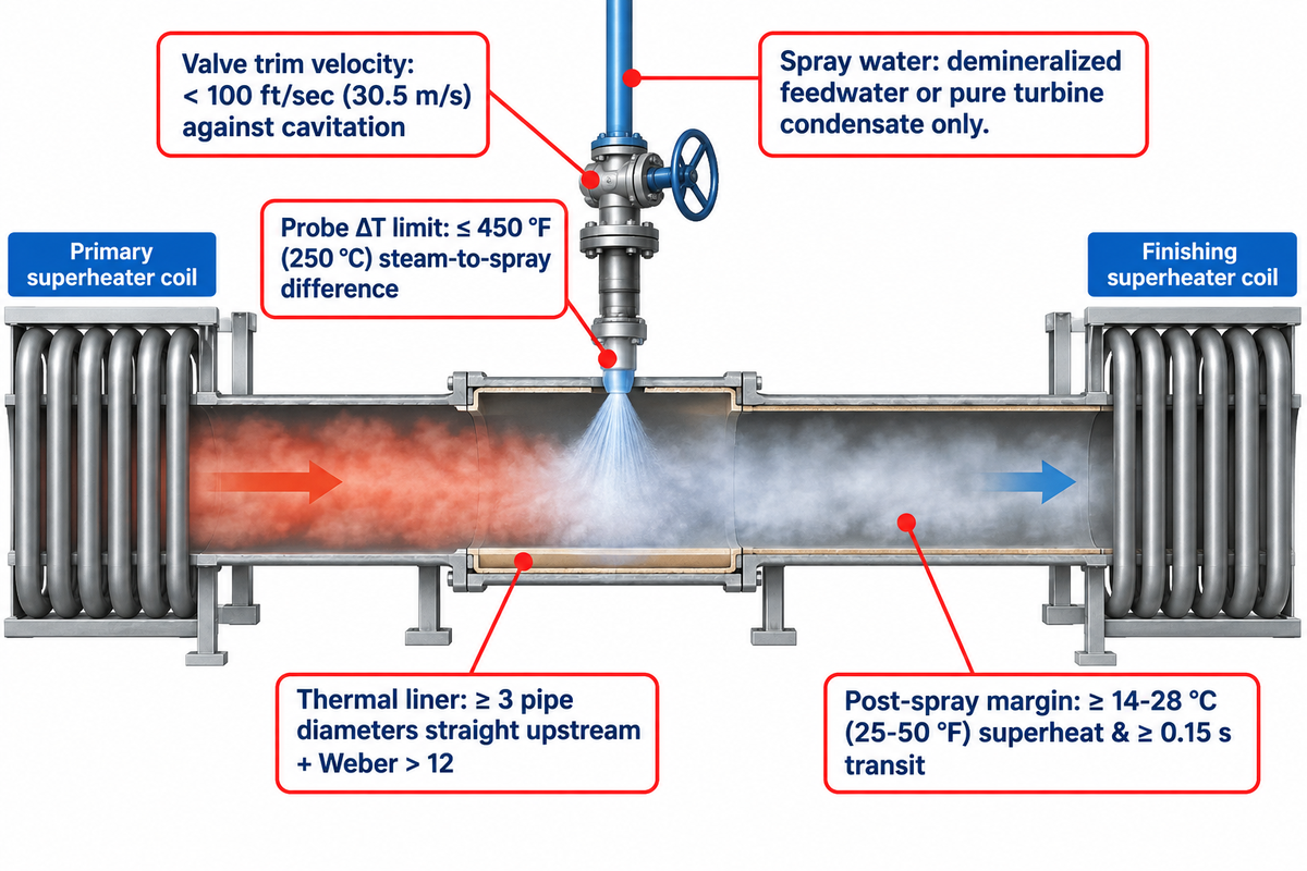
Interstage direct-contact spray attemperators hold final outlet steam temperature within ±3–5 °C by atomizing high-purity demineralized water between the primary and finishing superheater banks. Positioning the spray station between coil stages allows the downstream finishing bank to evaporate residual mist and equalize tube-to-tube metal temperatures.
What Is the Difference Between an Interstage Attemperator and a Downstream Desuperheater?
An interstage attemperator protects the finishing superheater metallurgy in the boiler circuitry, whereas a downstream pressure-reducing and desuperheating station (PRDS) conditions export steam for low-pressure plant users. In the USPTO F22G glossary, an attemperator cools superheated vapor via direct water contact or an indirect drum-shell heat exchanger.
The design of the spray nozzle determines the survivability of the spray hardware during thermal cycling. As mentioned in POWER Magazine’s HRSG desuperheater design guide, multinozzle probe attemperators shouldn’t be designed to have a steam-to-spray temperature difference greater than 450 °F (250 °C). Keep the velocity through the control valve trim below 100 ft/sec (30.5 m/s) to prevent cavitation erosion. Install a protective thermal liner with at least 3 pipe diameters of straight upstream run, and design droplet breakup so the Weber number holds above 12.
Spray Water Purity and Minimum Superheat Margin After Injection
Every microgram of dissolved solids injected through a direct-contact spray nozzle goes directly into the dry steam path, bypassing steam-drum separation. Softened makeup water containing sodium salts or silica plates out inside finishing bends and forms insulating scale blisters. Direct-contact spray water must be pure turbine condensate or demineralized feedwater.
Rapid load drops also introduce over-spray issues. Control loops must hold at least 14–28 °C (25–50 °F) of superheat immediately after the spray zone. Transfer piping also needs at least 0.15 seconds of transit time before the finishing superheater header. Predictive override logic that prevents spray injection when inlet steam to the finishing coil nears saturation is described in detail in US Patent US8904972B2.
Indirect surface attemperators overcome purity of water limitations found in plants lacking polished condensate. Instead of water being injected in steam, primary superheat vapor is passed through a submerged tube bundle in cooler boiler drum water. Drum water absorbs excess sensible heat through the tube wall. This way the main steam line isn’t contaminated.
Superheater Sizing Rules: Pressure Drop, Mass Velocity, and Safety Valves
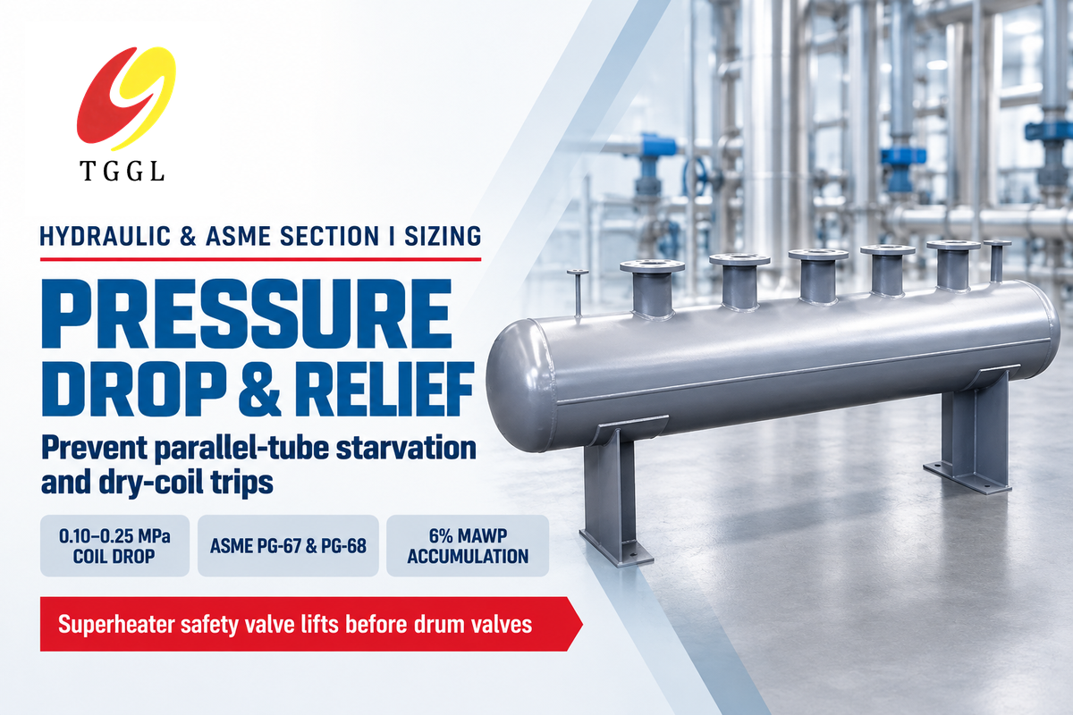
A correctly sized industrial superheater uses deliberate full-load steam pressure drops (0.10-0.25 MPa across medium-pressure coils, for example) to achieve uniform flow distribution. In addition, the outlet safety valve of a superheater is set to lift ahead of the steam drum safety valve. Both principles help achieve turbulent cooling flow through each parallel circuit.
Why Deliberate Coil Pressure Drop Prevents Parallel-Tube Flow Starvation
Reducing superheater pressure drops below 0.03 MPa is occasionally requested by procurement teams to save feedpump power. Low pressure drops reduce tube-side steam mass velocity, and allow headers to starve outer tube circuits. Starved loops overheat while mixed outlet headers still read normal average steam temperature.
Boiler drum maximum allowable working pressure (MAWP) is set by the turbine throttle pressure, plus pressure losses across lines, non-return valves, and full-load coil pressure drop.
Loop-to-loop steam balance can also be impacted by entry geometry of the feed nozzle. Headers that are end-entry create velocity head differences that result in downstream tubes being over-fed while tubes near the inlet are starved. For wide boiler turndown, it’s better to specify headers with radial or symmetrical dual inlets.
ASME Section I Safety Valve Sequencing: Protecting Coils During Load Rejection
The 2025 Edition ASME Boiler and Pressure Vessel Code Section I governs power boilers operating above 15 psig. Overpressure rules in paragraphs PG-67 and PG-68 mandate V-stamped direct spring-loaded safety valves and prohibit rupture disks. Total pressure accumulation during discharge can’t exceed 6% above MAWP.
If a downstream turbine trips, main steam stop valves will slam shut and furnace gas passes remain hot. If steam drum safety valves pop first, all generated vapor will vent from the drum and starve the superheater. Setting the superheater safety valve below the lowest drum valve will provide relief cooling flow through the coils.
Preventing Superheater Tube Failures: Startup, Carryover, and Creep
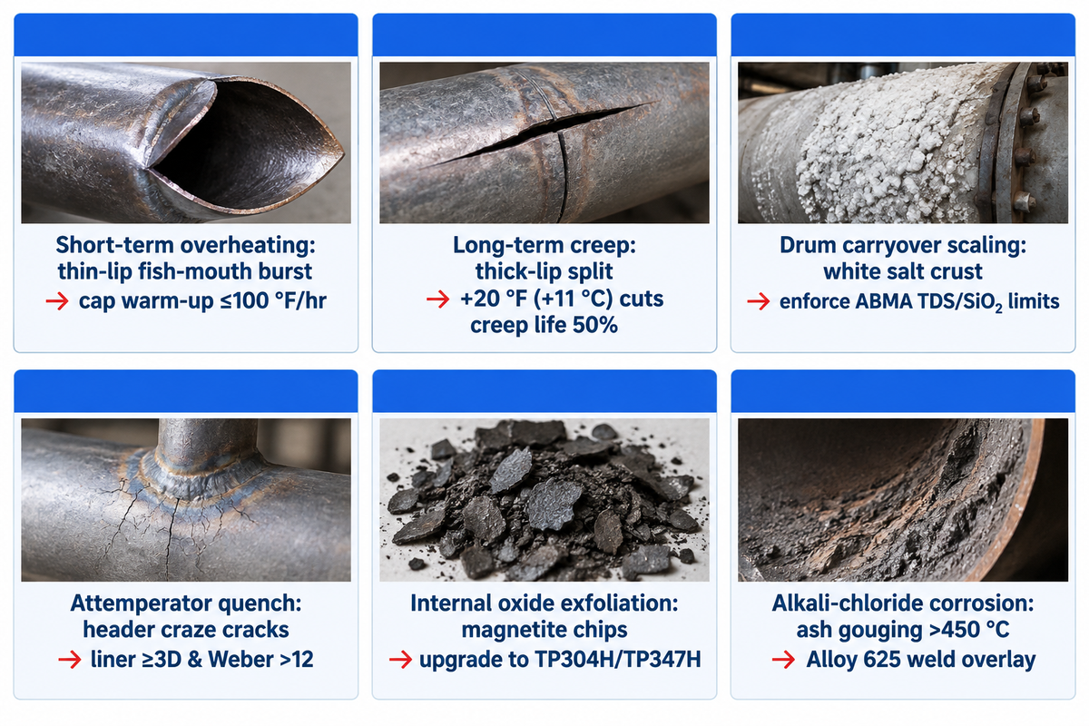
Preventing tube blowouts requires capping cold-boiler water warm-up at 100 °F/hr (55.6 °C/hr) and holding drum solids below ABMA pressure limits. Operators must also prevent metal temperature excursions from 10 to 20 °C from gas-baffle bypass. Most ruptures in the field are from starting-up dry-firing or deposit carryover rather than from the mill steel.
Cold-Startup Firing Limits and Vent-Valve Cooling Protection
During a cold light-off, burners fire into the furnace before boiler water boils and before main steam export opens. Until steaming begins, superheater heating surfaces receive zero internal cooling flow. National Board boiler startup and blowdown guidance caps cold boiler water warm-up at 100 °F per hour.
Operators open the superheater outlet startup vent before light-off and keep drum air vents open below 5 psig. Burners stay on low-fire interlock until gas temperatures remain safe and steady steam flow cools every loop.
A lance blowing 1.5-2.5 MPa steam + line condensate steam mix erodes through tubes. Installing half-cylinder sacrificial erosion shields in the first two tube rows in each lane stops steam cutting.
“A small increase in temperature may not seem like a big deal, but a 20-deg-F change in tube metal temperature can reduce remaining life by 50%!”
Diagnosing Short-Term Overheating, Long-Term Creep, Carryover Scale, and Alkali Corrosion
Fracture geometry allows for immediate determination of failure mode. Short-term overheating produces “fish-mouth” failures with thin lips. Long-term creep from chronic 11–20 °C overheating produces thick-edged axial splits, alligator-hide external scale, and spalling internal magnetite oxide.
Carryover deposits concentrate in primary inlet bends where wet drum foam evaporates into white salt crusts. Reeves in the National Board Bulletin notes that ABMA drum water limits start at 3,500 ppm TDS and 150 ppm SiO₂ for 0–300 psig boilers. Those limits tighten to 2,500 ppm TDS and 40 ppm SiO₂ at 451–600 psig, and reach 625 ppm TDS with 8 ppm SiO₂ at 901–1,000 psig. High chlorine biomass fuels combine with alkali salts to produce a melt above 450–480 °C steam temperature and require wide platen spacing.
| Failure Mechanism | Tube Inspection Signature | Primary Operational Trigger | Preventive Engineering Control |
|---|---|---|---|
| Short-term overheating | Wide thin-lip “fish-mouth” burst; elongated grains | Dry firing on fast cold start or condensate plug | Cap warm-up ≤100 °F/hr; open startup vent; drainable headers |
| Long-term creep rupture | Thick-lip longitudinal split; creep voids; OD swelling | +20 °F (+11 °C) metal over-temp cuts creep life 50% (CCJ) | Seal gas-bypass baffles; UT internal oxide thickness checks |
| Drum carryover scaling | White sodium/silica crust inside primary bends; blisters | High drum level, damaged demister, or excess TDS/SiO₂ | Enforce ABMA TDS/silica limits; automated continuous blowdown |
| Attemperator thermal quench | Circumferential craze cracking in header or liner | Leaking spray valve, ΔT >450 °F on probe, or <14 °C superheat | Thermal liner ≥3D straight run; We >12; low-superheat override |
| Internal oxide exfoliation | Flaking magnetite/spinel chips blocking bottom bends | T22/T91 operated near upper code oxidation limit | Upgrade finishing loops to TP304H/TP347H; borescope bends |
| Alkali-chloride ash corrosion | Fireside wall gouging beneath sticky salt deposits | High-chlorine straw, wood waste, or RDF fuels >450 °C steam | Cap steam temperature or co-extrude/weld-overlay Alloy 625 |
Specifying an Industrial Boiler Superheater: Alternatives and RFQ Checklist
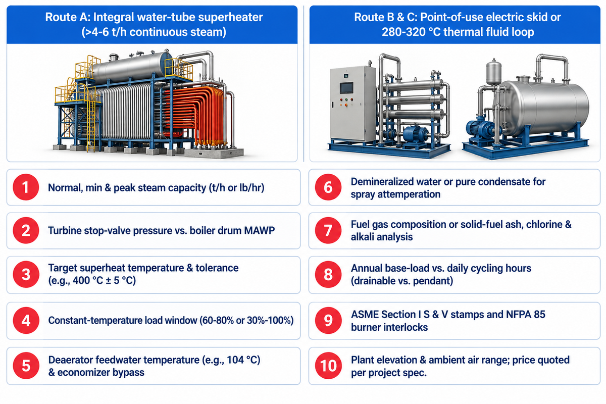
Correct sizing of a superheater requires delivery-point pressure, outlet steam temperature, control load window, feedwater inlet temperature, spray water source, and fuel. Leaving feedwater inlet temperature off an inquiry creates an unexpected cost. Colder feedwater requires more fuel to be fired, which increases convective outlet temperature.
Integral Boiler Superheater vs. Standalone Electric Superheater vs. Thermal Fluid Heater
An integral flue-gas superheater inside a water-tube boiler delivers the lowest energy cost whenever continuous steam demand exceeds 4–6 t/h. However, if a major part of a factory uses saturated heating steam and a small reactor requires 200 kg/h of 350 °C vapor, an electric steam superheater skid placed at point of use avoids running the central boiler house at increased pressure.
If a process only needs indirect sensible heating at 280 to 320 °C and there’s zero power generation by turbine, then superheating steam isn’t economical. Low-pressure liquid-phase oil loops eliminate high-pressure drum treatment and attemperation. A detailed comparison is made when high-pressure steam boilers are compared to thermal fluid heaters.
10-Point Engineering RFQ Checklist for Water-Tube Boilers with Superheaters
Include these 10 parameters in your superheated boiler RFQ datasheet
- State normal, minimum continuous, and peak rated steam evaporation capacity in t/h or lb/hr.
- Specify turbine stop-valve inlet pressure separately from drum MAWP so coil pressure drop is accommodated.
- Define target superheat temperature and control tolerance (e.g., 400 °C ± 5 °C) at the outlet header valve.
- Record the constant-temperature load window (for example, 60–80% continuous load or 30% to 100% cycling) over which temperature must hold flat.
- Provide deaerator feedwater inlet temperature (e.g., 104 °C) and note any economizer bypass operation.
- Confirm availability of demineralized water or polished turbine condensate for direct-contact attemperator spray.
- Attach complete fuel gas composition or solid-fuel proximate and ultimate ash analysis including chlorine and alkali metals.
- Indicate continuous annual base load hours vs. daily shift operation so engineers choose horizontal drainable coils vs. pendant coils.
- List required code stamping and combustion safety compliance, including ASME Section I “S” and “V” stamps, NFPA 85 burner interlocks, or local registration.
- Include plant elevation and ambient air temperature range for forced-draft fan sizing; equipment price and fabrication lead time are quoted per project specification.
Founded in 1976, Taiguo Boiler’s Grade A pressure-vessel manufacturing and testing facilities span 60,000 m² and export engineered water-tube steam systems to more than 100 countries. Our thermal engineers model furnace radiation, interstage attemperation, and SA-213 tube wall margins together before issuing general arrangement drawings.
Frequently Asked Questions About Boiler Superheaters
Does adding a superheater increase overall boiler thermal efficiency?
The addition of a superheater principally boosts the downstream Rankine steam turbine cycle efficiency and electrical output per ton of steam, as opposed to standalone boiler fuel-to-steam efficiency. Within the boiler envelope, final stack gas temperature leaving the tail-end economizer or air preheater governs fuel efficiency. Absorbing mid-pass flue heat simply shifts heat duty from evaporation to superheating.
Can a superheater be retrofitted onto an existing saturated steam boiler?
Water-tube boilers with accessible gas-pass cavities can accept a retrofit coil once flue-gas temperature, drum separator carryover, piping alloy limits, and PG-67/PG-68 safety-valve sequencing pass engineering checks. Compact three-pass fire-tube boilers don’t have safe gas-zone clearance for high superheat retrofits. Those plants typically install an external separately fired or an electric superheater.
What is the difference between a boiler superheater and a reheater?
The superheater receives saturated vapor steam directly from the boiler steam drum and heats it for the high-pressure turbine throttle. A reheater takes partially expanded intermediate-pressure exhaust steam returning from the high-pressure turbine cylinder and heats that lower pressure vapor before it’s admitted to downstream turbine stages. Utility power stations pair both coils, whereas industrial cogeneration boilers normally use superheaters alone.
What steam velocity is typical inside industrial superheater tubes?
Industrial convective superheater tubes generally operate in the range of 15 to 30 m/s linear steam velocity and 200 to 600 kg/(m²·s) mass velocity. That turbulent flow regime cools tubes adequately within coil pressure-drop constraints.
How do engineers inspect superheater coils during scheduled boiler outages?
Outage inspections consist of five key reviews to identify damage before unexpected tube failures. Inspectors first check along pendant and horizontal rows for bowed tubes, sagging support lugs, gaps in gas-baffles and sootblower steam-cutting erosion. Next, outside tube diameters are measured with micrometers to check for diameter creep and compare against the commissioning baseline. The remaining internal wall and thickness of the oxide scale in the hottest finishing loops are measured using ultrasonic probes to determine remaining creep-life. Borescopes are inserted through header caps to check lower bends for salt crusts, magnetite and other carryover materials. Lastly, phased-array ultrasonic tests are performed on dissimilar metal welds and thermal fatigue cracks are checked on header stub-tube welds.
Request a Custom Superheated Water-Tube Boiler Proposal
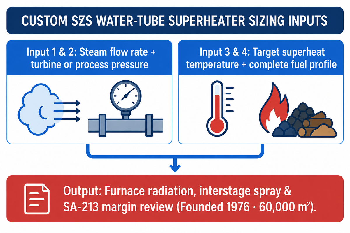
Please share with our engineering team your steam flow rate, turbine or process pressure, superheat temperature, and fuel profile. Review our SZS packaged water-tube steam boiler specifications for preliminary sizing. For engineering consultations and project pricing contact us directly.
References & Sources
- Spirax Sarco – Steam Engineering Principles and Heat Transfer: Superheated Steam
- United States Patent and Trademark Office (USPTO), CPC Subclass F22G: Superheating of Steam (2025.01).
- Massachusetts Institute of Technology (MIT), Section 18.5: Counterflow Heat Exchangers and Thermal Resistance.
- Dr. David N. French, Sc.D., National Board Bulletin, Microstructural Degradation and Boiler Alloy Oxidation Limits.
- William L. Reeves, P.E., National Board Bulletin, Boiler Blowdown, ABMA Water Limits, and Startup Guidelines.
- POWER Magazine, Designing HRSG Desuperheaters for Performance and Reliability.
- US Patent US8904972B2, Systems and Methods for Controlling Exhaust Steam Temperatures from a Finishing Superheater.
- American Society of Mechanical Engineers (ASME), 2025 Boiler and Pressure Vessel Code (BPVC).
- ARDT Engineering Reference, ASME BPVC Section I Power Boilers (PG-67 & PG-68 Overpressure Protection).
- Natalie Marini, HRST Inc., Combined Cycle Journal Issue 51, HRSGs: Beware Hidden Superheater, Reheater Overheating.